VERTICAL LOAD CAPACITY TEST
June 1, 1998
Steve Ross
Foam Concepts, Inc.
4750 E. Wesley Drive
Anaheim, CA 92807
Re: Lab. No 11101-98/1540
Dear Steve:
At your request, Ramtech Laboratories conducted testing to determine
the following:
A. Determine the vertical load capacity of the Expanded Plystyrene
Foam coated with unknown coating with metal insert, metal strips, and
metal covering when loaded with 8 x 12 steel plates at edges.
B. Determine the vertical load capacity of the Expanded Polystyrene
Foam coated with unknown coating with metal insert, metal strips, and
metal covering when loaded with 8 x 12 steel plate at interior of assembly.
Test
Specimen:
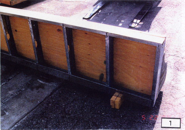
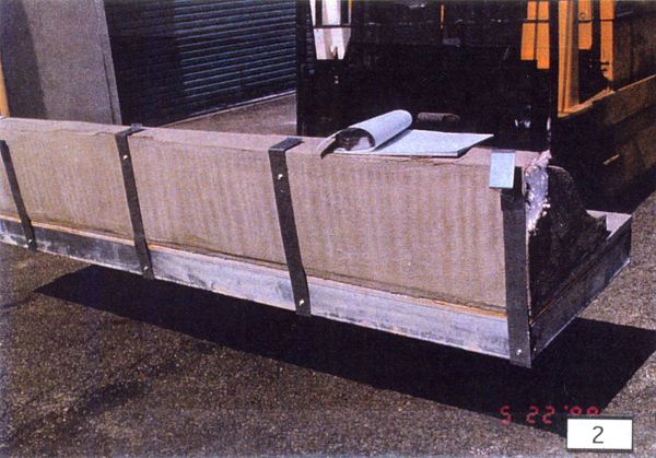
Four test assemblies, delivered to Ramtech Laboratories, Inc. by Foam
Concepts, were 24 inches wide by 96 inches long by 17.5 inches deep.
The metal inserts were located approximately 2- 5/8 inches from the
edge of the EPS. A 2-inch wide metal strip/clip of 0.063 inch thick
metal, including galvanizing, was installed perpendicular to the Styro-loc
inserts at 23 inch centers. The metal strip was bent around the edge
and extended down 3 inches. The end of the metal strip/clip was bent
outwards approximately _ inch to receive the flashing. At each intersection
with the Styro-loc inserts, the metal strip was fastened to the Styro-loc
insert with one hex head self drilling screw (0.125-inch shank x 7/8-inch
long). The EPS molding was adhered to the 7/8" thick plaster which
was fastened to the 3/8-inch thick, 3 ply-3 layer plywood sheathing.
The plywood sheathing was installed with face grain perpendicular to
steel stud framing with metal runners. The assemblies were delivered
to Ramtech Laboratories. None of the assemblies were witnessed by the
laboratory. See Attachment 1 for "assembly" details and data
on materials used in construction of the test assembly which was submitted
by Foam Concepts for inclusion in this report. The laboratory did not
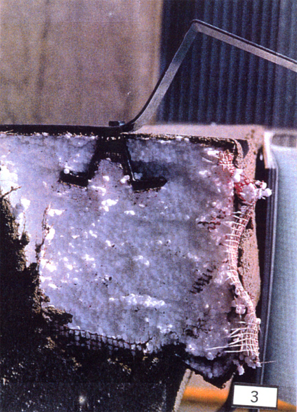
verify any materials or method of construction. See Photographs 1, 2,
and 3 for photographic details of the tested assembly.
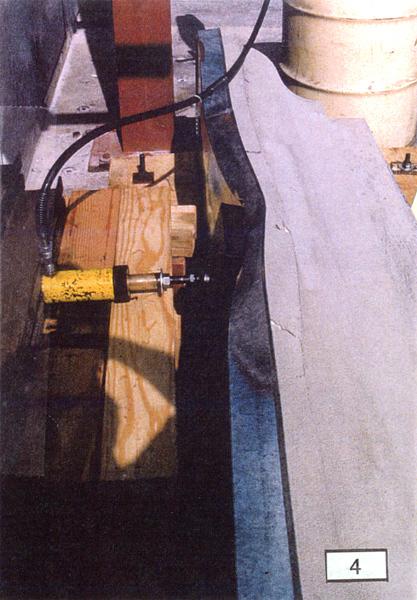
Test Program:
A 3/4-inch thick by 4 feet by 8 feet plywood sheet was screwed to the
steel stud framing of the assembly. The steel stud framing simulated
the parapet construction of the roof. The assembly/plywood was anchored
to a test slab so the molding/parapet was situated horizontally. A loading
system was established to load a 8 inch wide by 12 inches wide by 2
inch thick steel plate against the top of the assembly. The steel plate
was located so the top of the steel plate was approximately 1/4-inch
from the edge of the molding. The loading jack was placed at the center
of the steel plate.
For the end condition, the steel plate was located so the center of
the steel plate was 6 inches from the end. For the interior condition,
the steel plate was centered. The load was applied with a hydraulic
jack using a hydraulic pump. The pressure of the fluid was recorded.
The pressure gage was calibrated against the laboratory’s universal
testing machine.
Three full assemblies were tested. Each assembly was loaded at each
end and at the midspan.
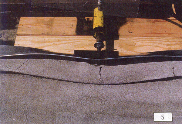
Initially the load was applied to a 3 inch disk, however, the disk indented
the metal covering and the coating/EPS foam. In order to test the assembly,
the 8 inch wide by 12 inches long by 2 inch thick steel plate was substituted
for the 3 inch thick disk. The steel plate was located so the total
steel area was bearing on the EPS foam molding and not on the plywood
edge.
Results:
Results are based on visual observation during the load application.
The results of both end and interior conditions are summarized in Table
I. The average load at which surface indentation was observed is the
1700 pounds and 2915 pounds at the end and the interior location respectively.
The average ultimate failure is 3200 pounds and 6330 pounds at the end
and interior location respectively. Based on observation of the test,
the design load should be based on the average load at first indentation
using an appropriate safety factor. Long term effectiveness of the adhesive/coating
should be investigated.
Please
give us a call if you have any questions.
Reported
Prepared by:
Ronald I. Ogawa, P.E.
Laboratory Consultant
Report Reviewed by:
David R. Macey
Laboratory Manager
|
|
EDGE
CONDITION |
INTERIOR
CONDITION |
Load
(psi) |
Load
(pounds) |
Test
1ER |
Test
1EL |
Test
2ER |
Test
2EL |
Test
3ER |
Test
3EL |
Test
1C |
Test
2C |
Test
3C |
500 |
1250 |
1 |
|
|
|
|
|
|
|
|
600 |
1500 |
|
|
2 |
|
|
2 |
|
|
|
700 |
1750 |
|
2 |
|
|
2 |
|
|
|
|
800 |
2000 |
|
|
|
2 |
|
|
|
|
|
900 |
2250 |
|
|
|
|
|
|
|
|
|
1000 |
2500 |
|
|
|
|
|
|
|
|
|
1100 |
2750 |
|
|
|
|
|
|
2 |
|
|
1200 |
3000 |
|
|
3 |
3 |
|
|
|
2 |
2 |
1300 |
3250 |
|
3 |
|
|
3 |
|
|
|
|
1400 |
3500 |
|
|
|
|
|
4 |
|
|
|
1500 |
3750 |
|
|
5 |
|
|
|
|
|
|
1600 |
4000 |
|
|
|
5 |
5 |
|
|
|
|
1700 |
4250 |
|
5 |
|
|
|
|
|
|
|
1800 |
4500 |
|
|
|
|
|
|
|
|
|
1900 |
4750 |
|
|
|
|
|
|
|
|
|
2000 |
5000 |
|
|
|
|
|
|
|
|
|
2400 |
6000 |
|
|
|
|
|
|
5 |
|
|
2600 |
6500 |
|
|
|
|
|
|
|
5 |
5 |
Ave.
at First Indentation
Ave. Ultimate Load
|
1700
Pounds
3201 Pounds
|
2917
Pounds
6333 Pounds |
1) Experimental test using 3 inch loading disk.
2) First observation of surface indentation.
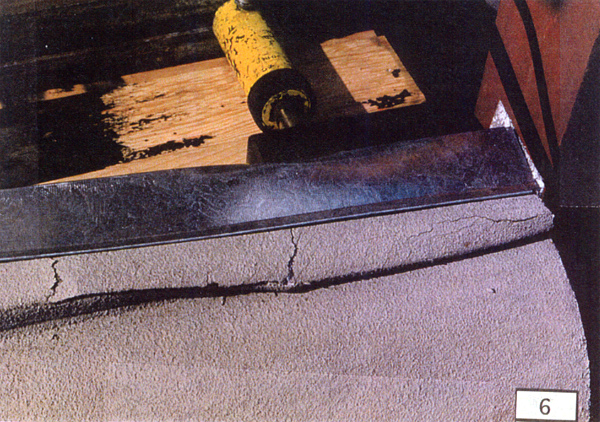
3) Crack and splitting of coating, EPS compressed substantially.
4) Steel stud buckling failure.
5) Ultimate failure. Surface damaged, coating cracked.
At interior, shear cracks directly below load point and approximately
13 to 15 inches on each side.
ER = Right end
EL = Left end
C = Interior or Center
----------------------------------------------------------------------------------------------------------
VISUAL DOCUMENTATION
Click thumbnail for enlargment